
Mechanical
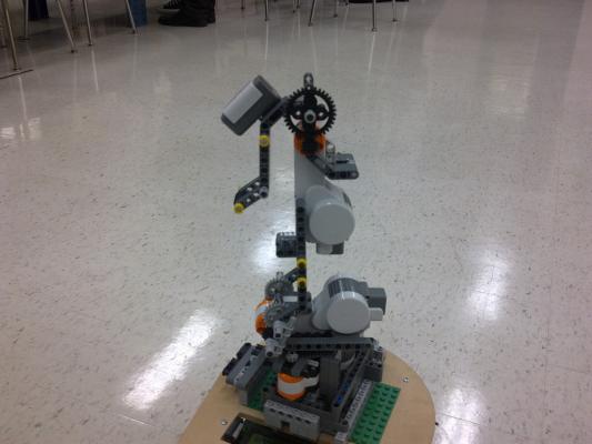
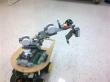
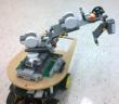
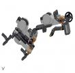
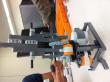
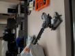
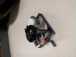
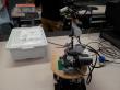
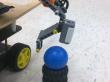
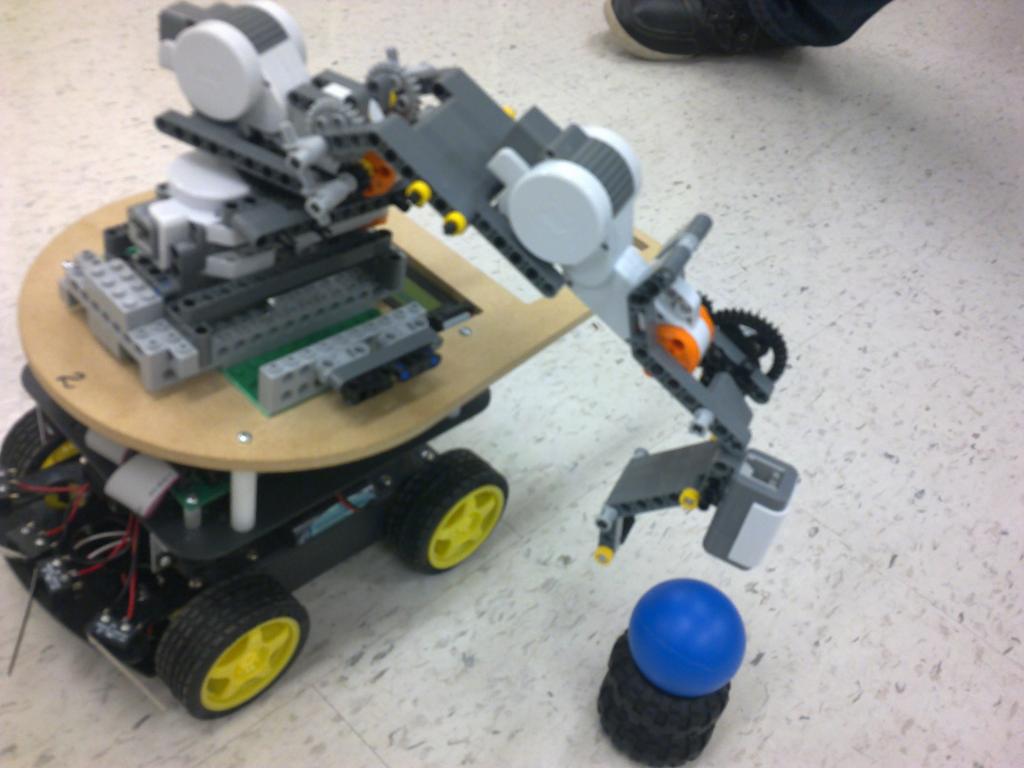
The mechanical design of the mobile robotic manipulator focused upon constructing a robotic arm which should be able to extend and search area specified by the project requirements. Robotic arm manipulator consisted of a 3 joint arm. The 3 servo motors included in Lego kit were connected at every link to control the motion of every link. As per the design specification, the robot arm needed to be mounted on top of the Ryerson MechBot which provided the arm with extra height which enabled the arm to search close to the robot.
In order to mount the arm on top of the MechBot, the connector blocs provided in the Lego kit were used to create a stable base for the robot arm to sustain the vibration caused by the model. The base of the robot arm was made to rotate about the y axis; the gear ratio of 7 was attached to the base servo motor. As the driving gear consisted of 8 and the technic turntable had 56 teeth’s. To obtain a better resolution, team consistently used the driving gear with less number of teeth’s as compared to the output gear. The gear ratio for the link 2 and link 3 was set to 4 and 3 respectively. By using the high gear ratio, meaning, using bigger output gear. Gear ratio provides a high output torque while decreasing the output speed which reduces the vibration levels. It was important to have a high torque to hold the links in position when the arm was searching for the object. The link 2 or the follower served the purpose of lowering the arm down as it extends and retracts whereas the link 3 served as the striker (hitting the ball into pocket).
Ryerson MechBot was programmed to follow the black tape by using the infrared sensors mounted at the bottom. The functionality of the whole system is as follow: The arm rotates and position itself anf than link 3 extracts in order to eradicate the possibility of hitting the frame when link 2 lowers down. Once the arm has positioned itself, a scan of the area is triggered. The scan radius is incremented every time till the ball has been detected, upon detecting the ball; all motors stop and link 3 strikes and ball.
Control
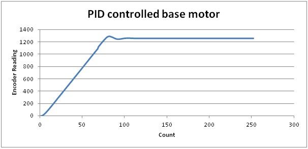
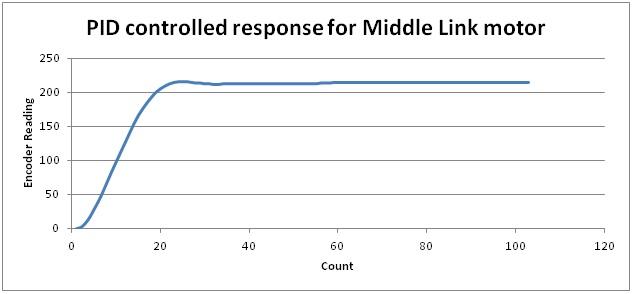
As long as the control system of the design mobile robotic manipulator is concerned, team decided to go ahead with implementing the PID controller for all 3 servo motors. In order to accurately position the arm and precisely scan the area defined for the location of the arm. As without the implementation of the PID controller, the motors were very unstable which caused vibrations at high rate which would make the system very unstable. As the two units were integrated to design the mobile robotic manipulator, it was important to make sure the system was stable and there were no loose connections and all the links were properly defined. Initially, once the MechBot had stopped at the T shaped intersection; robotic arm gets into position whose motion is performed by the PID controlled servo motors. Whereas, while scanning the area for an object, it was necessary to limit the speed of the arm. In other words, a very high speed of the rotation of the motor while scanning could make the system fail while detecting ball as well as too slow speed might stop the motor as soon as the edge of the object is detected. To overcome the issue, PID controllers were used which received the position and speed feedback from the motors and adjusted the speed of the motor with respect to the defined reference value for the rotation of the motor. The specific PID gain values for each motor were obtained by trial and error methods which are summarized underneath in Table 2. By using the PID controller, team was able to diminish the POS for all the motors controlling the motion of the arm and obtaining the faster settling time which reduced the vibration caused due to the actuation of the motors as compared to the vibration caused without the PID controller.
Table 4: Summary of the PID gains for all 3 motors.
| Kp | Kd | Ki | |
| MotorA (Base) | 1.5 | 0.05 | 4.5 |
| MotorB (Middle Link) | 2.0 | 0.05 | 2.5 |
| MotorC (Striker) | 0.35 | 0.05 | 0.5 |

Sensory
The final design of the system involved the use of light sensor, sound sensor and servo motor encoders for Lego Mindstorms NXT and infrared sensor, and edge detectors for the MechBot. The light sensor is used in the design to detect the ball in the area span defined in the project requirements. The range of the light sensor was obtained to be 23 to 36. The sound sensor is used to actuate the robot arm. MechBot beep range from 29 to 35 was obtained for the sound sensor. When the MechBot stops at the T shape black tape location, the MechBot is made to beep which is sensed by the sound sensor which in turn actuates the robot arm to perform its task. The robot arm consisted of 3 servo motors attached to 3 different links. Each servo motor was calibrated to rotate certain angle to position the arm into the position to detect the object. The first rotation takes place in servo motor 3 followed by second motor rotation and then the first motor rotates. During the first motor rotation the light sensor looks for the ball. If the ball is not sensed in the first sweep then servo motor 3 extends slightly, thus, extending the detection range of the light sensor horizontally and motor 1 rotates in the opposite direction and comes back to its initial position. If the ball is not found in the second sweep of the motor 1 returning to its original position, then, again motor 3 is made to extend and it repeats the actions again and again in the area span of the ball location until the ball is detected by the light sensor. When the light sensor detects the ball, motor 3 is actuated at a greater speed then the normal rotational speed to hit the ball into the target hole. After the ball has been hit, motor 3 retracts link 3 and motor 1 rotates to the middle of the right side of the MechBot and covers the right infrared sensor of the MechBot which is an instruction to the MechBot to start following the black tape again. Arm link 3 stays in front of the infrared sensor after the first ball hit until the MechBot stops again when all the motors are used for searching the ball and motor 3 for hitting it. Edge detectors at the bottom of the MechBot are used to follow the black tape path. For the MechBot line following operation the values for the edge detectors were again obtained by calibrating the MechBot several times, in order to make the whole system work smoothly.